I have a small 7litre oven that works a treat for Reflow of small boards.
I recently upgraded to a 20 litre oven with two element top and bottom. Rated at 1500Watts, there is able power to heat the area.

Front Shot of 20litre Oven
Having run the oven a couple of times manually I have concluded the following:
- The Temperature setting is a waste of time. it appears to be a simple bi metal switch and not a thermostat.
- The top needs some form of Insulation as the top lid gets really really hot.
- The Rack inside the oven is not attached to the door – bonus as far as I am concerned.
- I need to come up with some form of automated venting to cool the boards down.
- I may be able to fit another shelf and increase the throughput ( I am looking for some AL material with a 5mm grid of 5mm holes).

Simple Layout
An interesting note: the top elements are connected in series, as are the bottom elements. This is quite nifty as there is no need for a neutral return.
For now I will leave the oven as is that start the Controller.
I have been playing around with the Arduino IDE with the intention of teaching my girls Control theory. I have decided I would use this environment to develop the Oven Controller.
Maxim make a brilliant, if not slightly pricey Type K thermocouple digitises. it uses the SPI interface. ryanjmclaughlin has created an Arduino Library for the MAX6675.
Brett (aka br3ttb) had created a PID Library – Some may say all the fun has gone. Well maybe, but I still get to pull their work together and make my oven how I want it. I will be adding an LCD to give feedback on where you are in the cycle. Graphic would be super – otherwise 2×16 will be OK.
Update 1

Thermocouple Nut
Found an old thermocouple from a previous Jaycar project. The Type-K thermocouple is constructed with a 3.2mm Diameter Stainless Steel barrel and is an exact match for the MAX6675 for testing. I am not sure if this will be the final one I will use but for now it will suffice.When I was in the workshop, I realised how easy it would be to make a mounting nut for the thermocouple. Starting with a 3/8W bolt, I drilled a 3.2mm hole through the middle. I then drill a pilot hole in one the bolt head flats and tapped it with ISO M3.

Thermocouple with Nut installed
The MAX6675 performs cold-junction compensation and digitizes the signal from a type-K thermocouple. Direct
The data is output in a 12-bit resolution, SPI™-compatible, read-only format.
This converter resolves temperatures to 0.25°C, allows readings as high as +1024°C, and exhibits thermocouple accuracy of 8LSBs for temperatures ranging from 0°C to +700°C.
- Digital Conversion of Type -K Thermocouple Output
- Cold-Junction Compensation
- Simple SPI-Compatible Serial Interface
- 12-Bit, 0.25°C Resolution
- Open Thermocouple Detection

K type Thermocouple based Thermoneter

Whilst I await a Solid State Relay to come in, I have stated looking at the final schematic. I have allowed for two LCD modules. Currently I am testing in 4bit parallel mode, but would like to try a 3wire SPI display. the final design will only have a single display.
Follow features have been included:
- Nokia cable USB debug port
- Soft Power LED
- Heater Status LED
- DC Power supply requires attention
- Off board Solid State Relay – I am looking for a “Puck” type
- Emergency Stop to be implemented, either contactor or uController Interrupt
Update 2
I had previously noticed when I touch the MAX6675, the temperature increases by several degrees C. This effect was particular noticeable at room temp around 25 degree C. Tonight I added a fair amount of solder to my iron and help the thermocouple against the tip. The iron was set to 299degree c. This temp corresponded to 297degree C on the Arduino LCD. You got to be happy with that. touching the MAX6675 made the temp rise by only several degree C. The affect of warming the cold junction is not multiplied at high temperature.

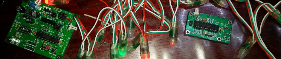
First Cut of PCB
I have started to put together and prototype PCB. it is almost there.
- This is based on the Arduino IDE
- It uses a Nokia USB data cable to program and also debugging.
- Two LCD options as available: 4bit Parallel bus of SPI
- The ISP port is configurable to serial LCD if you prefer.
- The Reflow routine is started by a single Push Button switch. The same PB is also the Stop / Halt button.
- Two indicators give Power and Heater status
- Uses the MAX 6675 k-type Thermocouple
- The whole board fits on a 2×2″ proto board form Seedstudio
Update 3
The Controller software will need to control the temperature for a number of conditions. I will be using the Kester Profile as a starting place. As each solder paste is different with very specific characteristics, the final temperature and ramp up rates will need to be reviewed and updated for the chosen solder. There are 4 distinct phases in the Reflow process:
- Preheat
- Thermal Soak
- Reflow
- Cool
The preheat section is where the solvent in the paste begins to evaporate, and if the rise rate (or temperature level) is too low, evaporation of flux volatiles is incomplete.
The thermal soak, is typically a 60 to 120 second exposure for removal of solder paste volatiles and activation of the fluxes , where the flux components begin oxide reduction on component leads and pads.
During the reflow phase the solder is a liquid. Flux reduces surface tension at the juncture of the metals to accomplish metallurgical bonding, allowing the individual solder powder spheres to combine. An insufficient time/temperature relationship causes a decrease in the flux’s cleaning action, resulting in poor wetting, inadequate removal of the solvent and flux, and possibly defective solder joints.
The cooling zone gradually cools the processed board and solidifies the solder joints. Proper cooling inhibits excess intermetallic formation or thermal shock to the components. For most DIY application the length of the cooling time is not critical. My web research shows most people open the oven door to assist in cooling, however is it vital that the oven is not knocked or subject to vibrations whilst entering the Cooling zone. These may cause components to move off their pads, or worst still create cold solder joints. This is another reason to ensure the tray is not attached to the door.
(Source: most of the above description was taken from Wikipedia )