El Light Costume

Our daughter’s youth group decided to have a party one evening and requested the girls came as Disney characters.

  • On Wednesday night Rose announced she wanted to go as on Quora of Tron.
  • That night I found a close seller of Blue EL wire.
  • On Thursday Morning, the Wife headed out and picked up 2x 3m battery operated EL wire kits.
  • I have a spare 80mm LED ring light
  • As technical director of this clan must task was complete. The wife and eldest daughter took over from there.
  • On Friday Night Rose headed off to her party.

Posted in Other Hardware, ramble | Comments Off on El Light Costume

DC Power Distribution

With a lot of decentralized controllers, I need to run both DMX and power to a lot of places. Some times it is convenient to daisy-chain the power, others is is best to run a separate feed from the Power supply.
For the latter solution, I designed this Power Distributor panel.

Dc Power Distribution Panel

2.1mm DC power connector

The panel is configured as 2 separate circuits and allows 2.1mm DC Barrel type connectors to be soldered directly on the PCB.

Constructed Units

Revision B
These DC Distribution boards have served me well.  But with so many different controllers in use, I decided to recut the improve the unit.  Rarely did I actually run two different voltages, so having 2 halves was wasted.  In variable I would splice in a fuse in the  controllers.  And I was always getting out the multimeter to see if the unit had power.

DC_Distribution_Opt1

2.5mm Barrel sockets only

So I I ditched one half and decided to add onboard fuses. I went with the mini Auto fuses.  I added an LED and finally I modified the DC Power library model to take both DC power sockets or 2 pin terminal blocks. The following is the result.

DC_Distribution_Opt2

Mixed Outputs

Posted in Light Controllers, Other Hardware | Comments Off on DC Power Distribution

RGB + Strobes Mini Tree

Let me say first and foremost, I am still trying to find good uses for RGB strip lights out on the display and not against a flat surface or tacked up under an alcove.

This is another attempt.

Some time late last year, I purchased some tomato trellis’ for the wife’s herb garden. At the time I thought, ” I am going to have to buy some of them for me too”

I also scored what I think is a half decent price on some waterproof RGB Strips – 40m for AUD120 delivered.

Cost estimation now sits at:
tomato trellis – $11
2.5m LED Strip – $15
3 or 4 Ch DMX DC Controller – $6 to $20
ACL strobe – ~ $5 (I think ) maybe.

An Open Canvas Tomato Trellis

RGB strip cable tied to trellis

Last night I hacked one together and am happy with the results.  The LEDs are mounted on a single side of the strips and thus are very directional.  However there is a pleasant glow on the back side of the strips also.

Next the Controller to be added. followed by the Strobes.  Two Choices come to mind:  The MIC 3ch specials would be more than adequate for the Strips.

MIC 3ch DMX

OR my own 4ch DMX controller allowing Some Strobes to be added inside the Tree.

Top View of Semi populated Controller


To add Strobes, I will need to tap off +5v from the on-board regulator. Not a big issue but required a little further hacking.

Posted in AVRs, DMX, Other Hardware | Comments Off on RGB + Strobes Mini Tree

RGB Kittys

Back in 2007 I stumbled across a house decoration that had fading RGB lanterns high lighting a path to the front porch.   John Chapman of Engineering Solutions Inc Developed a suite id LED Based RGB Pixel projects/products.  the one that particularly inspired me was Point Sources.

Not knowing anything at all about PIC, it was then I decided to make an AVR equivalent unit wit ha couple of variations.  These shots are the finished products. There are a couple of options for the LEDs, a single 4 pin Common Anode RGB LED or 3 separate LEDs.  the whole unit runs of 5Volts.  the LED current are limited to about 20mA each, as per the AVR AtTiny2313 specification.

The RGB Kitty Schematic is available for reuse.

By shorting X3, the controller goes into Address mode and sets the DMX Start Address to the DMX Values of (Ch1 + Ch2).

Panel of 10 Kittys - Front

Panel of 10 Kittys - Rear

Why Kitty?  When designing these I always wanted them to be more than pixel sources, as Pixel conjures up images of small point sources of light.  I wanted Ping-Pong ball sources of diffused light.  As I was nearing competition of the circuit design, my cat’s eyes caught my attention.  ( I know I am hopeless cat person) Thus Kitty Eyes became the project name.  that eventually was shortened to RGB Kittys

For Sale.

I have about 100 (10x panels) Version 1 boards left from the first run.  These are available for sale.


Version 2

Version 2 in planning phase.

I intend to make the following changes:

  • Add a 78l05 voltage regulator ( probably a SOT-223 case as they appear to be the best priced units currently
  • Replace X3 wit ha SMD switch, AND add a track to pin5 of X1 &X2.
  • Change X1&X2 spacing to 0.1′ spacing
  • Reduce the size significantly and rationalise the SMD component positioning


Posted in AVRs, DMX, Light Controllers | Comments Off on RGB Kittys

Falling Icicles

Falling Icicles made their debut in my area 2009.  Initially they were hideously expensive and hard to find.  But secretly I always knew I would get some.

Then least year Big-W  / K Mart started sell small falling Icicles  sets ( 300mm long light bars) that that ran independently of each other.  closer inspection revealed some kind of controller at the top of the PCB. Unfortunately I didn’t have the time nor money to purchase a number of the ready made units.

Falling Icicles BaukoLites Style

I hacked together a design that will allow considerable flexibility.  The general concept is to create a small DMX based 16ch Controller that uses LED Constant Current drivers.  The Controller will be mounted at the top of the Icicles.   The LEDS will NOT be PCB mounted, but rather will be wired to suspend inside  1/2″ PVC tubing.

16Ch LED Falling Icicles

16ch DMX LED Icicle Controller

Let me stop here and say the biggest influence on my design was N1ist’s Color Sticks over as DIYC.com.  The two projects share a great number of common components.  Details of Mike’s project can be found here.

The Schematic for the controller available  here. <place marker only>

Making the LED strings

The final LED spacing has been on my mind for a while now.  I figure I need to address a number of areas:

  • LED viewing angle
  • LED Spacing (distance between LEDs in a single segment)
  • Segment spacing (distance between segments of LEDs)

25mm & 35mm Segment Spacing

The LED view area has a large affect on the the final product.  Most 3mm LEDs are very directional.  Sanding the LED surface may be a solution to diffuse the LEDs.  3mm Top hats may also be the best way to go.

Construction

THe blank PCBs arrived today.  Nice job.

Assembled Falling Icicle Controller


Software Considerations

I suddenly realised the Top LED segments MUST be channel 16.  this is no big issue but is makes chasing Lights easier if this is the case.  The SPI will clock out channel 16 first.

If I can I would like to build in some smarts in to the Controller.

The easiest options it to treat this like every other 16 channel controller and allocate 16 DMX channels.  This offers a would of flexibility.

However the more I think of how I want to use these icicles the more I reckon a simple single channel will be able to achieve everything I want.  So here is what I am thinking:

DMX Start 

Address

DMX End
Address
Function DMX Start
Address
DMX End
Address
Function
0 9 All lights Off 100 109 All lights Off
10 19 Chase at 500mS rate 110 119 Chase 3 LEDs at 500mS rate
20 29 Chase at 450mS rate 120 129 Chase 3 LEDs at 450mS rate
30 39 Chase at 400mS rate 130 139 Chase 3 LEDs at 400mS rate
40 49 Chase at 350mS rate 140 149 Chase 3 LEDs at 350mS rate
50 59 Chase at 300mS rate 150 159 Chase 3 LEDs at 300mS rate
60 69 Chase at 250mS rate 160 169 Chase 3 LEDs at 250mS rate
70 79 Chase at 200mS rate 170 179 Chase 3 LEDs at 200mS rate
80 89 Chase at 150mS rate 180 189 Chase 3 LEDs at 1500mS rate
90 99 Chase at 100mS rate 190 199 Chase 3 LEDs at 100mS rate
200 209 All on dimmed at 5% 210 219 All on dimmed at 10%
220 229 All on dimmed at 15% 230 239 All on dimmed at 30%
240 249 All on dimmed at 50% 250 255 All on dimmed at 100%

the down side to such a method is remembering specific functions when programming vixen.

Posted in AVRs, DMX, Light Controllers | Tagged , , | Comments Off on Falling Icicles

8 Channel RGB LED Flexible Strip Controller

My leaping arches were a disaster this year. originally constructed by cutting 36″ lengths of white rope light that was bent back on itself, to form a 18 section, about 8 of the 32 sections failed to turn on!  So stuff them They were left turned OFF! &*%#$@)*%^Y

Now the season is over, I have had to time to rethink what I would like to do with the leaping arched.  I like the efficiency of LEDs, so an Olde School version using 100 LED strings with 3 or 4 colours would be a good option.  However, I am yet sorted out a decent supply of LED Strings and a conservative cost would be $10 x 3 x 8 x 4 = $960 for the four arches.  That is too “ouch”

So to begin with I will settle with some sections of RGB strips like these. Sample LED Strip. Depending on the strip model, flexible LED strips are available in 12V or 24v versions, with the 24v version being preferred as the current draw is lower.

Either way I am going to need an 8 channel RGB controller small enough to be added to the base of the leaping arches and light enough to be actually mounted on the arch.

The heart of the new Controller is a small AVR, ATTiny2313.  This little AVR is packed with a stack of I/O modules, including a USART capable of receiving DMX.  The DMX is received by a RS485 transceiver and connected directly to the USART RX port.

I have been using Ceramic Resonators for a while now on DMX controllers.  Whilst their probably are not in specification over all temperature ranges, they have worked well to date.  The main advantage of the Ceramic Resonators is cost and the need not to use external capacitors.

This controller will use a 3 wire SPI interface to controller the 24 output channels.  The Tiny2313 implements the SPI bus in a non standard manner and will required attention in terms of software. We will return the Output cct shortly.

The power supply requirement +12 to 36 volts and should be as efficient as possible. A member over on DIYC.com, RPM, recommended I check out the LM2574 Smart Switcher form Nat Semi,.  RPM uses the same device on his 16channel DC Dimmer.  The cct is pretty basic, and National provides tables and graphs to select the switching components.  The SMPS will provide power only to the micro-controller and association logic circuits.

The final section of the circuit is the output drive. I had already decided I wanted to use FETs due to their very low On resistance.  This in turn means the dimmer power consumption is minimised.  To drive the FETs I use serial in, Parallel out Shift Register 74HC595.  This was also borrowed from RPM on DIYC.com.  There are 3x HC595, configured as a huge 24 bit serial in – parallel out shift register. (Note I have only shown 2 sections to conserve space, full schematics will be available below in the very near future.)  The FETs are pretty standard, IRLL014 by International Rectifier.  I choose this one for the following reasons:

  • HEXFET
  • UltraLow R(on)
  • Vdss = 55v
  • Id = 2A
  • Pretty low cost @ AU0.34 each

The artwork is shown below.

After a discussion on DIYC.com, the suggestion was made to add the possibility of using a 78L05 linear Regulator and  not fitting the LM2574 Simple Switcher.  While the 78L05 addition is not shown above, it was included in the final design that went to the PCB Fab.

I am not too sure if I should say the above artwork is “very pleasing” but I will.
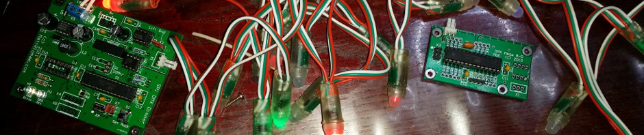
Built unit


April 2011
I finally received the RGB strips from China.
Two test are required:

  • Voltage drop of the +12 track with all 8 channels are ON
  • Temperature rise of both Tracks and components

After a 36hour Burn in test ( with all channels fully ON) the voltage drop from the input supply connector X13 to Pin 1 of X1 was about 0.2 volts.

Hopefully a mate will drop off his IR thermometer soon.

[nggallery id=9]

8ChRGB Red test (4 channel only)

8ChRGB Purple test (4 channel only)

Posted in AVRs, DMX, Light Controllers | Comments Off on 8 Channel RGB LED Flexible Strip Controller

HOW-TO: Soldering SOIC devices by hand

The secret to good SMT soldering is not to heat the IC too much and not to use too much solder.

The following is the method I use to solder SOIC IC. Some of the steps and techniques will be applicable to other Surface mount Devices, but hopefully these will be covered off in other How-Tos
Tools required:

  • ESD work environment
  • ESD Tweezers
  • Soldering Iron with a chisel tip (I use 2-2.4mm tip)
  • Fine Solder 0.5mm diam is really good, 0.7mm diam will do
  • Liquid Flux Pen
  • Plastic Eraser

Now for the good stuff:

  1. Clean the PCB pads if it has been sitting around for a while. A Plastic Eraser is good for this.
  2. Place the board on an ESD work matt.
  3. Tin 2 diagonally opposite pads, for example 16 and 8 or 20 and 10.
    • You just want a small amount of solder in the pads and I try and make one of them a ground pin.
  4. Dab the tinned pads with your flux pen
  5. Place the IC on the pads, paying particular attention to the pin alignment to the pads.
    • Don’t forget to check Pin1 is on the right pad.
  6. Holding the IC in place by gently pushing downward on the IC body with a pair 0f tweezers, solder the pins on the tinned pads. Do not add additional solder.
  7. Now check the IC for alignment again, cause now is the time to make corrections.
    • To realign, gently apply the soldering iron to a pad and when the solder if molten, move the IC a small amount. Reapply heat to the other pad to release any stress in the IC leg.
  8. Place a straight section of solder against the un-soldered pins of the IC. I actually place it so that the Solder doesn’t touch the pad, but sits on the lowers section of the IC leg.
  9. Starting with the pin next to the tinned pad, gentle place the soldering iron tip against the pad and solder
  10. When the solder melts, count “1 and 2” and remove the tip and move to the next pin
  11. DO NOT Push any solder into the joint, ever. You end up with too much solder
  12. Repeat for the other side of the IC.

If this sounds complicated, then believe me it is not.  Have a go.  you will find you get in the swing of this real quickly.  As I stated in the beginning, the secret to good SMD soldering is not to heat the IC too much and not to use too much solder.  Good luck.

Posted in TOT - tools of the trade | Tagged , , | Comments Off on HOW-TO: Soldering SOIC devices by hand

DMX Load

A fair number of controllers have DMX loads built in. I don’t use them. I am always worried id leave a load jumpered when I extend the DMX line further out.
Either way you need to get to remember to add a DMX load at the end of each run.

With the rise of more RJ 45 being used for DMX wiring, especially in this hobby, I thought it was time to make a couple of RJ45 loads. They are a cinch to make and give immediate confirmation there the load is in place. Also as the load is plugged into the “Out”, you can’t get any loads left jumpered mid-stream.

[nggallery id=8]

Posted in DMX | Tagged , | Comments Off on DMX Load

TOT – Reflow Oven

I have a small 7litre oven that works a treat for Reflow of small boards.

I recently upgraded to a 20 litre oven with two element top and bottom.  Rated at 1500Watts, there is able power to heat the area.

Front Shot of 20litre Oven

Having run the oven a couple of times manually I have concluded the following:

  1. The Temperature setting is a waste of time.  it appears to be a simple bi metal switch and not a thermostat.
  2. The top needs some form of Insulation as the top lid gets really really hot.
  3. The Rack inside the oven is not attached to the door – bonus as far  as I am concerned.
  4. I need to come up with some form of automated venting to cool the boards down.
  5. I may be able to fit another shelf and increase the throughput ( I am looking for some AL material with a 5mm grid of 5mm holes).

Simple Layout

An interesting note: the top elements are connected in series, as are the bottom elements. This is quite nifty as there is no need for a neutral return.

For now I will leave the oven as is that start the Controller.

I have been playing around with the Arduino IDE with the intention of teaching my girls Control theory.  I have decided I would use this environment to develop the Oven Controller.

Maxim make a brilliant, if not slightly pricey Type K thermocouple digitises.  it uses the SPI interface.  ryanjmclaughlin has created an Arduino Library for the MAX6675.  

Brett (aka br3ttb) had created a PID Library – Some may say all the fun has gone.  Well maybe, but I still get to pull their work together and make my oven how I want it.  I will be adding an LCD to give feedback on where you are in the cycle. Graphic would be super – otherwise 2×16 will be OK.

Update 1

Thermocouple Nut

Found an old thermocouple from a previous Jaycar project.   The Type-K thermocouple is constructed with a 3.2mm Diameter Stainless Steel barrel and is an exact match for the MAX6675 for testing.  I am not sure if this will be the final one I will use but for now it will suffice.When I was in the workshop, I realised how easy it would be to make a mounting nut for the thermocouple.  Starting with a 3/8W bolt, I drilled a 3.2mm hole through the middle.  I then drill a pilot hole in one the bolt head flats and tapped it with ISO M3.

Thermocouple with Nut installed

The MAX6675 performs cold-junction compensation  and digitizes the signal from a type-K thermocouple. Direct
The data is output in a 12-bit resolution, SPI™-compatible, read-only format.
This converter resolves temperatures to 0.25°C, allows readings as high as +1024°C, and exhibits thermocouple accuracy of 8LSBs for temperatures ranging from 0°C to +700°C.

  • Digital Conversion of Type -K Thermocouple Output
  • Cold-Junction Compensation
  • Simple SPI-Compatible Serial Interface
  • 12-Bit, 0.25°C Resolution
  • Open Thermocouple Detection

K type Thermocouple based Thermoneter


Whilst I await a Solid State Relay to come in, I have stated looking at the final schematic.  I have allowed for two LCD modules.  Currently I am testing in 4bit parallel mode, but would like to try a 3wire SPI display.  the final design will only have a single display.
Follow features have been included:

  • Nokia cable USB debug port
  • Soft Power LED
  • Heater Status LED
  • DC Power supply requires attention
  • Off board Solid State Relay – I am looking for a “Puck” type
  • Emergency Stop to be implemented, either contactor or  uController Interrupt

Continue reading

Posted in Other Hardware, TOT - tools of the trade | Tagged , , | Comments Off on TOT – Reflow Oven

4Channel Dmx DC Controller

I have a couple of RPM’s 4ch AC DMX SSRs.  They are a great concept for when you need a small channel count in a remote part of your display.

I predominantly use LEDs for displays. This means DC is king.  So recently I set out to build a simple DC controller that would need to be small and have reasonable switching capabilities.

I cam up with this list of requirements

  • Smaller is better
  • Minimum of 2 Amps per channel
  • Input supply voltage to be a minimum of 36Vdc, 48Vdc if possible
  • Standard Diag lights
  • Surface mount components

A couple of weeks ago, Rockby Electronics‘ weekend sale listed some small bulkhead plastic cases for 75 cents each.  That was a steal!  I bought 80!

The following story details the approach I took to create what will be the end result, starting with the initial PCB Design.

The Design has progressed somewhat.  The final layout was changed somewhat to allow better cable entry from the box.

Top View of Semi populated Controller


To make assembly easier, I had the PCB made in panels of 6.

Panel - Bottom Side - All SMT

Panel - Top Side - All the Leaded components


So how does it Perform?


Posted in AVRs, DMX, Light Controllers | Comments Off on 4Channel Dmx DC Controller